

Views: 0 Author: Site Editor Publish Time: 2026-07-31 Origin: Site


What Each Component Tells You
Prepare the Equipment and Inspection Site
How to Use a 512Hz Sewer Camera Locator Step by Step
Improve Accuracy and Troubleshoot Locating Problems
FAQ
Conclusion
A sewer camera can show a blockage, damaged joint, root intrusion, or collapsed section, but video alone does not reveal where that defect is beneath a floor, driveway, or yard. A compatible 512Hz locator closes this information gap by detecting the signal transmitted from the camera head. Accurate locating still depends on correct preparation, controlled sensitivity, and repeated verification. The following procedure explains how to complete a sewer camera inspection, identify the camera’s surface position, manage interference, and document findings before repair work begins.
A 512Hz locating setup combines visual inspection with above-ground signal detection. The pipe camera provides live footage, while a sonde inside or behind the camera head transmits a 512Hz signal. A handheld locator detects that signal from the surface, and a distance counter records how much push cable has entered the pipe. These components support one another, but they do not provide identical information or replace the operator’s judgment.
Component | Primary Function | Practical Limitation |
|---|---|---|
Camera head | Shows the interior condition of the pipe | Cannot independently show the surface location |
512Hz sonde | Transmits a signal from the camera position | Requires a compatible receiver |
Handheld locator | Detects the sonde above ground | Accuracy changes with depth and interference |
Distance counter | Measures inserted push-cable length | Does not account for every bend or direction change |
Monitor and recorder | Displays and documents inspection footage | Recorded distance should still be verified onsite |
The sonde is not a GPS device, and the locator does not create a complete underground map automatically. It identifies the position of the transmitting camera head rather than directly detecting every section of the pipe. Likewise, a 20-meter counter reading means that approximately 20 meters of cable has left the reel, not that the camera is 20 meters in a straight line from the access point. Combining video observations, cable distance, the expected pipe route, and the surface signal produces a more dependable result.
The QYTeco 512Hz Sewer Camera System uses a 21mm 1080P camera head, a 13.3-inch monitor, an integrated distance counter, and a fiberglass push rod available in several reel lengths. Its 512Hz transmitter and self-leveling function are selectable options, so the required configuration should be confirmed before the job begins. The system is designed for pipes measuring approximately 50–150mm in diameter. These details matter because camera diameter, cable stiffness, frequency, and pipe size all affect whether the inspection and locating process can be completed efficiently.
Start by choosing a sewer camera that fits the access point, pipe diameter, bend radius, and expected inspection distance. A large camera head may provide good visibility in a main sewer line but struggle to pass through a narrow plumbing branch or tight elbow. For lines measuring approximately 25–50mm, QYTeco’s Mini Plumbing Camera uses a 12.8mm head and a 4.8mm fiberglass cable. Selecting an appropriately sized plumbing inspection camera reduces the risk of lodging the head, forcing the push rod, or ending the inspection before reaching the defect.
Test the complete sewer camera and locator combination above ground before inserting the head. Turn on the monitor, confirm that the camera image is stable, activate the sonde according to the system instructions, and set the receiver to 512Hz sonde mode. Hold the locator near the camera head and verify that its signal changes predictably as the distance increases or decreases. This simple test helps reveal depleted batteries, damaged connections, an inactive transmitter, or an incorrect locator mode before the camera is deep inside the line.
Clean the lens, adjust the LEDs, zero the distance counter, and begin recording before advancing the push rod. Note the cleanout location, pipe direction, building layout, and any visible surface structures that may affect the route. Manhole covers, reinforcing steel, vehicles, fences, electrical equipment, and nearby utilities can alter the signal or create misleading responses. If excavation may follow the sewer line inspection, the sonde location must never replace required utility-marking procedures or applicable safe-digging practices.
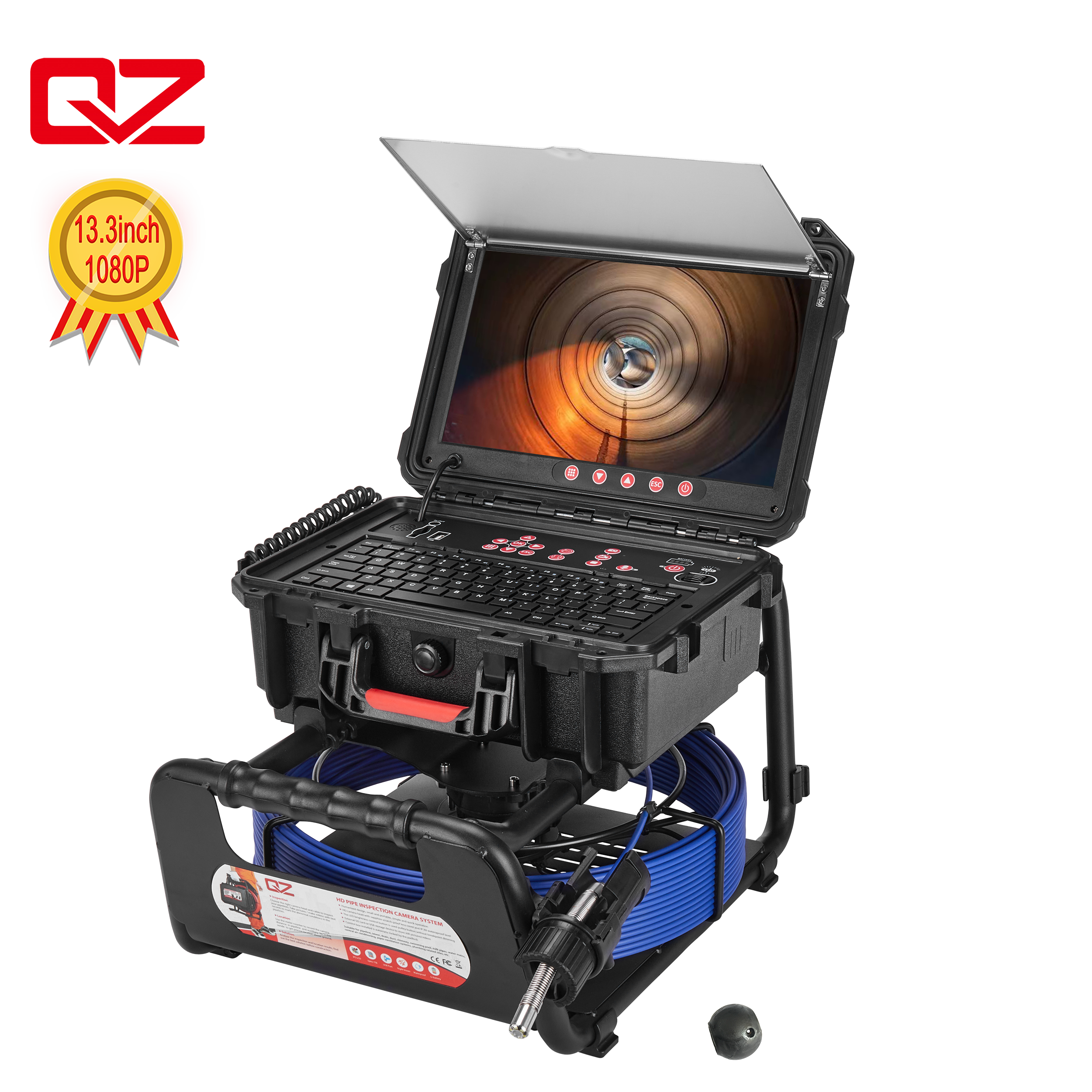
Feed the push rod slowly through an approved cleanout or inspection opening while watching the screen continuously. Avoid forcing the cable through a bend because excessive pressure can damage the rod, camera connection, or pipe fitting. Observe joints, changes in pipe material, standing water, deposits, roots, cracks, offsets, and other conditions that may explain the drainage problem. Record important observations together with the distance-counter reading so that each defect has both visual and measured references.
Pause when the camera head reaches the exact feature that must be located from above. Move slightly forward and backward to confirm that the selected position corresponds to the blockage, broken joint, pipe belly, connection, or structural defect. A self-leveling view can make orientation and documentation easier because the footage remains upright as the head rotates. QYTeco’s Self-Leveling Pipe Camera combines a 21mm head, 1080P imaging, an optional 512Hz transmitter, and a 5.3mm cable for pipes measuring approximately 50–150mm.
Keep the camera stationary and verify that the 512Hz sonde remains active. Set the handheld locator to sonde mode at the matching frequency rather than a passive utility mode or active line-tracing mode. Begin with a broad search range or higher sensitivity if the receiver provides adjustable settings. The purpose of this stage is to enter the probable target area, not to mark the final point immediately.
Use the access point, distance counter, known pipe direction, and building plan to define a sensible search zone. Walk slowly across this zone while holding the locator in the orientation required by its manual, keeping the receiver height and movement consistent. Sweep from more than one direction instead of following the first increase in signal strength. A repeatable response that aligns with the expected pipe route is more useful than a single loud or visually strong reading.
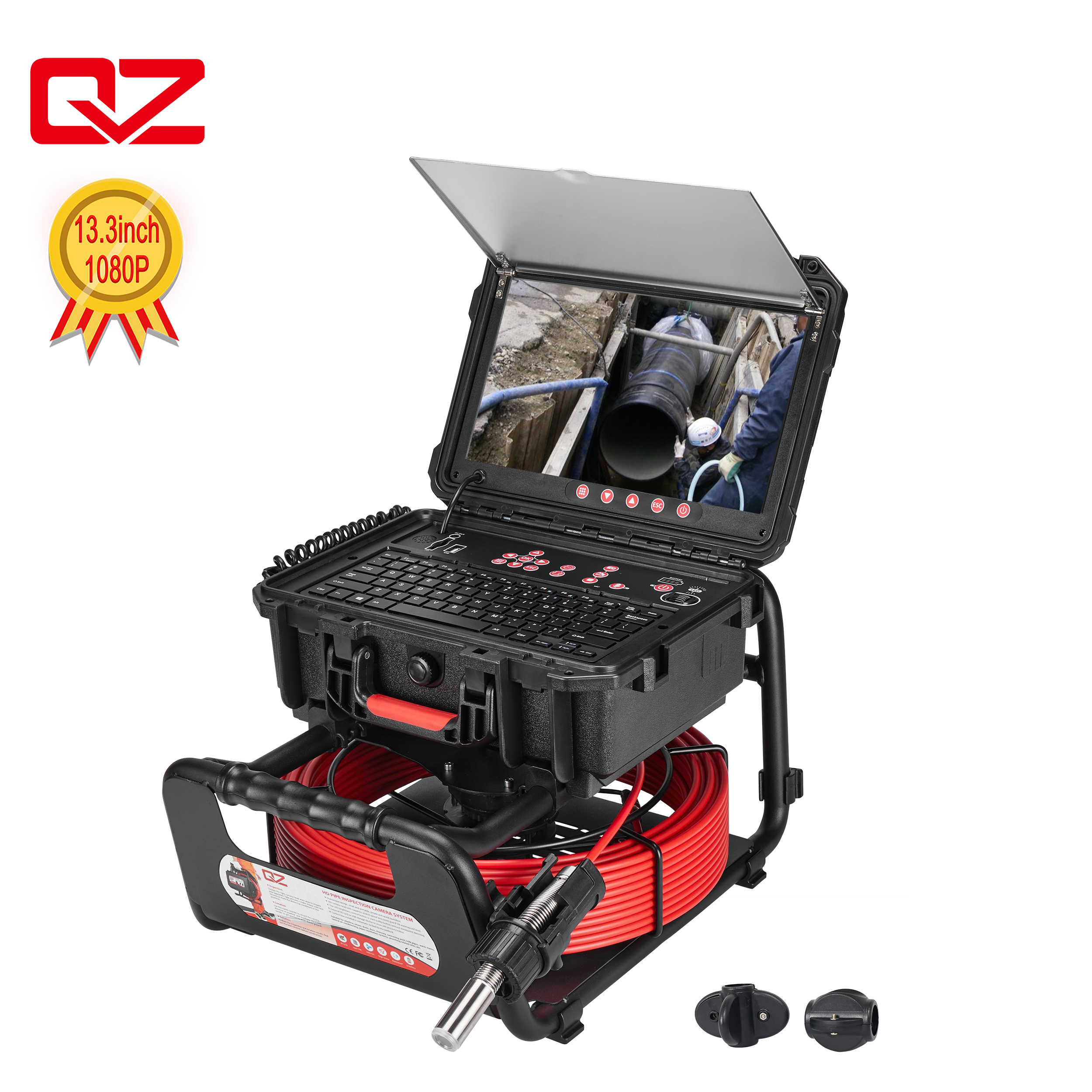
As the signal becomes stronger, reduce the locator sensitivity gradually. High sensitivity is useful for finding the general area, but it may produce a broad response that makes the final position difficult to distinguish. Continue approaching from several directions and look for the strongest signal that can be reproduced consistently at a lower setting. Slow scanning and controlled sensitivity adjustments are more reliable than marking the first apparent signal peak.
After identifying a likely surface point, move the camera head a short, controlled distance inside the pipe. The detected surface response should move in the same general direction and by a plausible amount. Return the camera to the defect and repeat the locating sweep to see whether the strongest response returns to the original mark. This movement test is one of the most practical ways to distinguish the actual sonde from nearby metal, another transmitter, or electromagnetic interference.
Some locators calculate an estimated depth, while others primarily display signal strength or directional information. Follow the receiver’s specified positioning method and take several measurements rather than relying on one number. Compare the result with the pipe route, access-point elevation, camera distance, and expected drainage slope. Depth and accuracy can vary with transmitter output, soil conditions, pipe material, concrete reinforcement, nearby conductive lines, and electromagnetic activity.
Mark the verified surface location with paint, chalk, a flag, or another method appropriate for the site. Record the camera distance, locator settings, estimated depth, pipe direction, defect type, date, and nearby reference points. Save the relevant sewer camera inspection footage and still images so the repair team can compare the underground finding with the surface mark. Before cutting concrete or excavating soil, confirm required utility responses and follow local safety procedures rather than using the sewer camera mark as excavation clearance.
Pipe and surrounding materials can have a major effect on locating performance. Plastic, clay, and other nonconductive pipes generally allow the sonde field to reach the surface more clearly, although depth and nearby utilities still matter. Cast iron, steel, and reinforced concrete may weaken or distort the signal, resulting in reduced effective range or inconsistent depth readings. Water inside the pipe does not necessarily prevent sonde detection, but the overall combination of pipe material, burial conditions, transmitter power, and interference must be considered.
When no signal appears, return to the access point and test the locator near the camera head again. Confirm the frequency, sonde mode, transmitter activation, system connections, and battery condition before assuming that the pipe is too deep. If the signal is detectable above ground but disappears after the camera enters a particular section, move the head backward toward the last confirmed location. A returning signal may indicate shielding or distortion around a metallic pipe section rather than complete equipment failure.
Several strong peaks usually suggest excessive sensitivity, field distortion, nearby conductive objects, or another active signal. Lower the sensitivity, remove movable metal objects where practical, and scan the area from perpendicular directions. Keep the camera still while comparing readings, then move it slightly and confirm that the suspected peak follows the camera. Distorted fields can become stronger or weaker around buried metal, which is why the highest reading alone is not sufficient proof of location.
Finally, confirm what the sewer camera package actually includes. A product described as having a 512Hz transmitter may contain the sonde but not the handheld receiver. The locator must support the same frequency and provide the operating modes required for the intended sewer line inspection. Buyers should also compare camera-head size, push-rod diameter, cable length, counter function, recording capability, and field serviceability instead of choosing a system only because “512Hz” appears in its description.
Using a 512Hz sewer camera locator successfully requires more than following the strongest signal. The operator must match the transmitter and receiver frequency, inspect the pipe methodically, reduce sensitivity near the target, and verify the result from multiple directions. Camera movement, distance records, footage, and site observations should all support the final mark. Shenzhen QYTeco is a sewer camera manufacturer and supplier with documented product development, production, assembly, quality-control, and testing processes, offering inspection configurations for different pipe sizes and locating requirements.
A: It is the operating frequency of the sonde near the camera head. A compatible above-ground locator detects this signal to estimate the camera’s position.
A: The sonde locates the camera’s current position, not every section automatically. Operators must move the camera and repeat measurements to map multiple points.
A: Not necessarily. Some systems include a 512Hz transmitter but sell the compatible receiver separately, so the complete package configuration should be verified before ordering.
A: Nearby metal, electrical activity, reinforced concrete, excessive sensitivity, or another transmitter may distort the field. Scan from several directions and verify by moving the camera.
A: No. It locates the camera sonde inside the inspected pipe and does not identify every buried utility. Required utility-marking and excavation procedures still apply.


